Key Concepts
Before you learn about implementing Catalyst circuits, it is important to understand some fundamental concepts in detail.
Components of a Circuit
The workflow design of a Catalyst circuit contains various components that help you orchestrate the logic and data flow in it.
Circuit States
A state is a particular condition that the circuit is in, at a given point of time. It defines a specific task or process that is executed in that stage of the circuit.
Circuit states can be broadly grouped under two categories:
-
Flow Controls: The flow control states orchestrate the flow of logic and data in the circuit. The following flow control states are available in Catalyst circuits:
- Pass
- Branch
- Parallel
- Wait
- Batch
- Success
- Failure
-
Functional: The functional states define the actual operations that need to be executed in the circuit. The following functional control states are available in Catalyst circuits:
- Function
- Circuit
We will discuss each of these states in detail in the next section.
A circuit traverses from one state to the next during its execution in a step-by-step manner. Logic and data flow occurs between each state in the circuit. The following properties exist in the configuration of each state:
- Previous state: The state that was traversed previous to the current state
- Next state: The state that will be traversed after the current state
The start of a circuit is marked by a key called Start, and the end of the circuit is marked by a key called End, in the circuit’s schematic flow diagram.
In the circuit’s JSON code, if a state does not mention the next key, it is the last state, and if a state is not referred as next in any other states, it is the first state of the circuit. You can refer to this section for a sample JSON code snippet.
Input, Output, and Result
A Catalyst circuit, in general, accepts an input when it is initiated and provides an output after it has executed. These are called the circuit input and circuit output.
-
Circuit Input: When you initiate the execution of a circuit, you will need to provide input to the circuit as key-value pairs in the JSON format. Since Basic I/O functions, which are the functional elements of a circuit, process input in the JSON format, the circuit input supports the same. This input provided during the initiation is passed to the first state in the circuit.
-
Circuit Output: The input JSON is then processed and traversed through the states in the circuit, based on its workflow design and architecture. After the last state has been traversed, Catalyst generates the final output of the circuit obtained after its execution completes.
You can view detailed execution logs and history of each execution from the console.
You can manipulate the input JSON and provide custom input to each state for processing, or select a portion of the output from each state’s processing to pass on to the next state based on your needs. You can also dynamically include the results of a processed state to the input JSON and pass it on.
These are done by the following properties of a circuit state:
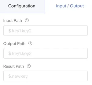
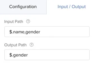
- Input path:
The input path allows you to select a portion of the state’s input, and it passes it to the state’s task for processing. For example, let the input JSON of a state be:
{
name: Amelia Burrows
gender: F
age: 33
}
If you only want to send the name and gender variables as the input to a state, say a function, you can configure the input path of the function as $.name,gender. This refers to the JSON objects name and gender as the input path.
Catalyst imports the external JsonPath library to define the input path, output path, and the result path of a state in a circuit. Therefore, you can use all the expressions supported by JsonPath in your path definitions. Refer to this GitHub documentation on the JsonPath syntax.
- Output path:
The output path allows you to select a portion of the state’s output, and it passes it on to the next state for processing. For example, let the output JSON of a state be:
[
26,
"John Kemper",
  {
    "streetAddress": "Sunshine Avenue",
    "city": "Austin",
    "postalCode": "630-0231"
   }
]
You can select only the values of the age and name objects (26, John Kemper) from the output to pass on to the next state, by configuring the output path of the state as $.age,name.
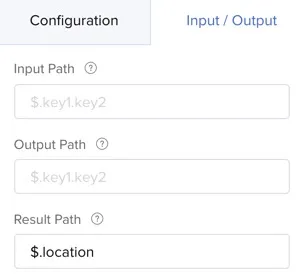
- Result path:
The result path allows you to combine parts of the state’s input and the result of the state’s execution, as the output of the state. In other words, you can append the state’s result to the input JSON provided to the state, and modify the JSON. You can then pass this modified JSON as the state’s output to the next state for processing.
For example, let a function in a circuit process an input JSON that contains two objects called presentDays and totalWorkingDays. The output of the function’s processing generates a new value that is assigned to a variable called attendancePercentage in its output.
If you want to include the value obtained for attendancePercentage to the original JSON, you can provide the result path as $.attendancePercentage. The JSON will then be modified as:
[
  	180,
  	200,
  	90
	]
Where the value for presentDays is 180, totalWorkingDays is 200, and attendancePercentage is 90.
You can now pass this output to the next state for processing.
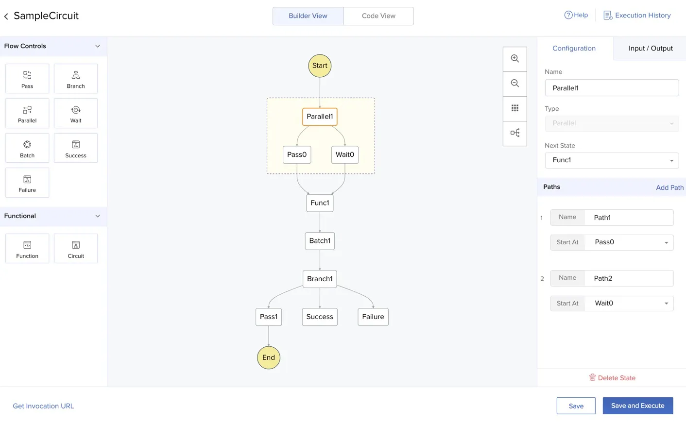
Circuit States
As discussed previously, the circuit states can be grouped as flow control states or functional states. Let’s learn about each state in detail, and the configurations available for them.
This is the Builder View of a circuit. This section displays images of the configurations available for each state for your reference. To learn about the steps involved in creating a circuit and adding states in it, refer to the Implementation section.
Function
The function state is a functional element that represents a Basic I/O function. The function states are the core elements of a circuit, where a large portion of the logic is processed. All the other flow control states help you manipulate and customize the functions processing in a circuit.
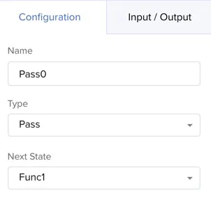
You can enter names for all the states in a circuit, select their type, and select their next states while configuring the circuit in the console. You can delete a particular state by clicking Delete State below the configuration window.
When you select a function state, you can link it with a Basic I/O function configured in your Catalyst project by selecting it from the dropdown list.
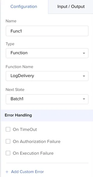
Error Handling:
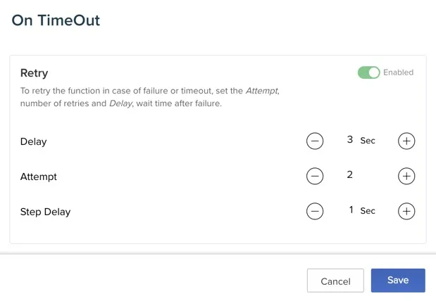
The function state supports error handling to handle frequently occurring errors during the function execution. You can configure the actions to be taken during On TimeOut, On Authorization Failure, or On Execution Failure errors.
Click the checkbox of an error to enable it. All three error handlers support two default actions: Retry and Fallback. Click Retry or Fallback to enable them.
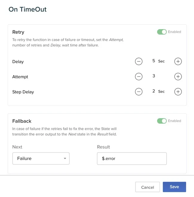
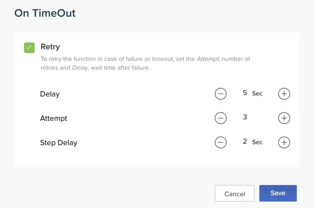
The retry option ensures that the function execution is re-tried if that particular error occurs. You can configure the following properties in retry:
- Delay: Defines the time duration to wait before attempting the first retry
- Attempt: Defines the number of retry attempts to be made
- Step Delay: Defines the time duration to wait in between each attempt
The fallback option is used to set the action to be performed when all retries fail. This allows you to choose another state in the circuit to fall back to, when the retries fail.
Select a state from the drop down list to fallback to. Enter the path of the error trace under Result in the JsonPath syntax while entering this value. If the retry attempts fail, the circuit is set to the state configured here, and the error trace is generated. Click Save to save the handler.
The error handlers of all three default errors (On TimeOut, On Authorization Failure, On Execution Failure) have the same actions and configuration.
In addition to these default error handlers, you can define custom errors and handle the actions to occur upon receiving that error. You can code the function to process the custom error handler for a specific error that is met.
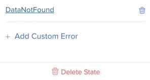
Click Add Custom Error under Error Handling in the state’s configuration.
Enter a name for the custom error in the pop-up window’s header. You can select either Error Code or Error Message as the exception type. Provide an exception value in both cases. This will be the error message or code displayed when the error occurs.
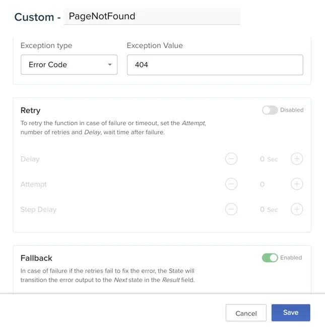
You can enable and configure both Retry and Fallback for a custom error, like the default error handlers. Click Save after configuring it.
You can delete a custom error by clicking the delete icon.
Catalyst considers all HTTP status codes of the 200 series (200-299) as a successful execution for a Basic I/O function. If the function returns a status code in its response other than one of the 200 series, for example 502, Circuits will check the function’s error handling configuration for a custom error handler match. If a match is found, the logic configured for it will be executed. If the error code has not been handled, the circuit execution will be considered as a failure.
If you configure an error message, you can handle it however you need in the function’s logic.
Input/Output:
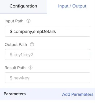
You can configure the input, output, and result paths of a function state, as discussed in this section. You can also pass configure individual parameters to be passed to a function from this section.
You can select a specific set of parameters from the JSON circuit input to be passed to the function using the input path.
For example, let the input JSON passed to a circuit be:
"personalDetails":{
      "name":"Patricia Boyle",
      "age" : 26,
	   "address":"13, Orchid Lane, NY"
	},
"company":"Zylker Corporation",
"empDetails":{
"department":"Sales",
"designation":"Sales Manager"
}
If you need to pass the entire input to a function that is configured in the circuit as its payload, you can pass it to the circuit in the default way, while initiating the circuit. The key-value pairs in this input will be passed as the function’s parameters automatically.
If you require only a certain set of parameters to be passed to the function, you can configure the key of the parameter set, in the input path. For example, to pass the company and empDetails parameters alone, you can provide the input path to the function as: $.company,empDetails using the JsonPath syntax.
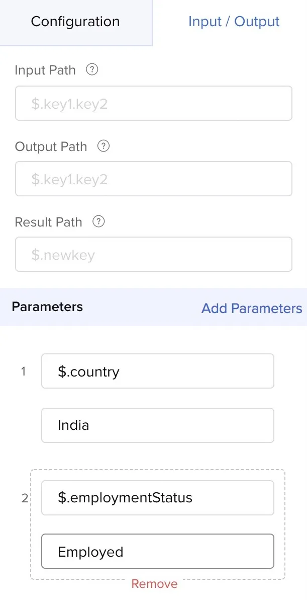
You can also choose individual parameters to be passed to the function using the Parameters option. This option also allows you to pass additional values to the function that are not present in the JSON circuit input. Click Add Parameters to add a parameter and value.
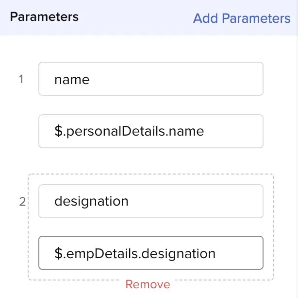
For example, you can choose to pass only the name and designation to the function as parameters by configuring name and designation as the parameter keys and entering their paths in the JsonPath syntax as parameter values. You can remove a parameter by clicking Remove.
A Catalyst Basic I/O function’s response delivers the function’s output using the key output. When you configure a function in a circuit, you need not provide the output key explicitly in the function’s output path or result path.
Catalyst handles it by default, and delivers the output value automatically. If the circuit is configured to pass the function’s output to the next state after it, Catalyst automatically passes the output as the payload without any additional configurations.
For example, this JSON output of a function,
[
180,
90
]
is passed as the JSON input to the next state in the circuit as the payload during the circuit execution.
The execution log of the circuit provides links to the function that was executed and to the Catalyst Logs that contains the log of that specific function, for a function state.
Circuit
The circuit state is a representation of a nested circuit. You can process another circuit inside the parent circuit. When a circuit state is triggered, the child circuit is executed as configured in Catalyst Circuits.
You can also have nested circuits inside a child circuit. This enables you to configure simple and independent circuits for different purposes, and nest them within each other, rather than configuring one complex circuit for a complicated workflow pattern.
You can select the child circuit using its reference name from the Circuit Name drop down box in a circuit state. You will also be able to select the parent circuit itself for a circuit state. This executes the same circuit in a loop, whose logic you can configure.
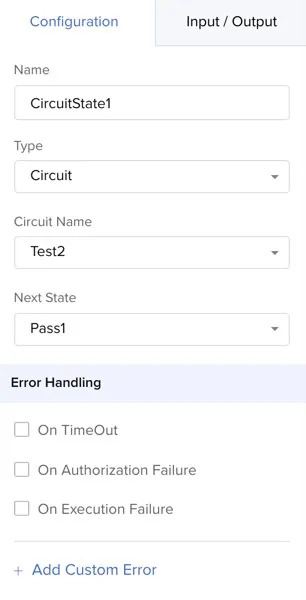
The circuit state also supports default error handlers, and custom error handlers, as the function state. However, unlike the function state, the circuit state has only one action for its default or custom error handler: Retry. Refer to the Functions section for information about retry and custom error handlers.
You can write your own logic for the actions to be performed if all retry operations fail. For example, you code for the circuit to re-execute, or end it and send a notification about the issue.
You can manipulate the JSON data that is passed through the circuit state by configuring its input path, output path, or the result path, as described in the previous section and in the Function state.
The execution log of the circuit also provides a link to the nested circuit’s log for easy reference.
Pass
The pass state is a flow control state that enables the data of a circuit to pass from one state to another. By default, it simply passes on the JSON input data from its previous state to its next state.
You can manipulate the JSON data that is passed through a pass state by configuring its input path, output path, or the result path, as described in the previous section. For example, you can select a portion of the JSON data alone to be passed on to its next state by configuring its input path.
The pass state also has a new property called result in addition to the input, output, and result paths. This is not available for any other states.
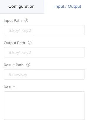
The result property enables you to append a new object to the JSON, and pass the modified JSON to the next state.
For example, in an input JSON that contains the objects name, age, and gender, you can append a new parameter called location as $.location in the pass state’s result path. You can enter the value for location in the result box. The modified JSON will then contain the objects name, age, gender, and location.
Branch
The branch state enables you to set up conditions in the circuit’s workflow, and execute tasks based on those conditions. You can create branches in the flow of the circuit if the input data meets a specific set of criteria, and execute different states in each branch.
For example, assume that the output of the state prior to a branch in a circuit generates the values for a JSON object status as complete or incomplete. If the status is complete, you require the circuit to traverse to a success state. If the status is incomplete, you require the circuit to traverse to a failure state.
To achieve this outcome, you can add a condition as $.status == ‘complete’ and configure the ‘Go To’ to a success state. Similarly, you can add another condition as $.status==‘incomplete’ and set it to a failure state.
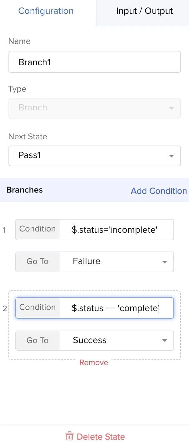
You can add a condition by clicking Add Condition, then you can enter the condition and select the next state of that branch. Configure that state as the type that you require. You can remove a condition by clicking Remove.
The following operators are supported by Catalyst for the conditional statements in the branch state:
| Operators | Description |
|---|---|
| == | Left is equal to right (note that 1 is not equal to ‘1’) |
| != | Left is not equal to right |
| < | Left is less than right |
| <= | Left is less than or equal to right |
| > | Left is greater than right |
| >= | Left is greater than or equal to right |
| =~ | Left matches the regular expression [?(@.name =~ /foo.*?/i)] |
| in | Left exists in right [?(@.size in [‘S’, ‘M’]) |
| nin | Left does not exist in right |
| size | Size of left (array or string) should match right |
| empty | Left (array or string) should be empty |
The conditional statements also support the following built in functions:
| Function | Description | Output |
|---|---|---|
| min() | Provides the min value of an array of numbers | Double |
| max() | Provides the max value of an array of numbers | Double |
| avg() | Provides the average value of an array of numbers | Double |
| stddev() | Provides the standard deviation value of an array of numbers | Double |
| length() | Provides the length of an array | Integer |
| sum() | Provides the sum value of an array of numbers | Double |
You can also use the JsonPath syntax to access an object’s path in the condition.
The branch state has a default pathway that you can link with the next state of the entire branch state. If none of the configured conditions are met, the default branch is followed, and that state is executed.
You can configure the input and output paths of a branch state as described previously.
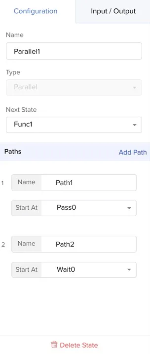
Parallel
The parallel state enables you to process multiple states in parallel, instead of in a sequential manner.
When you assign two states to be processed in parallel, both the processes are initiated at the same time, and their input, output, and results are processed and generated concurrently. The states are also exited at the same time. You can check the parallel processing from the execution logs after the circuit has been executed.
For example, if you require two functions to be executed in parallel, you can add two states for them respectively, and configure them as paths in the parallel state.
You can add paths in a parallel state for each state that needs to be executed in the parallel processing by clicking Add Path. You can enter the name of the paths and configure the state types.
You can configure the input, output, and result paths of a parallel state as discussed previously.
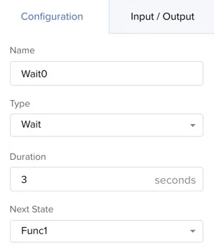
Wait
The wait state enables you to pause the execution of the circuit for a particular duration of time, before resuming it again and traversing to the next state.
For example, if you require a function’s execution to be triggered with a delay of three seconds after the processing of the previous state, you can use this. You can set the duration of delay in seconds in its configuration.
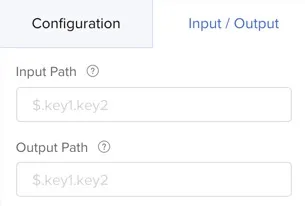
You can configure the input and output paths of a wait state as discussed previously.
Batch
The batch state enables you to execute a function or a circuit in batches as multiple jobs in an iterative manner. Batch processing allows you to process a large volume of input or tasks in sets, so that the server is not overwhelmed with heavy loads.
If the input contains an array of JSON objects, you can process each JSON object simultaneously using the batch state. This batch state enables the associated function or circuit to be triggered in parallel multiple times, based on the number of jobs configured.
For example, if a Basic I/O function is configured to send an email to a large number of customers, you can process it in the batch state and set the number of jobs to 10, so that the function is executed 10 times simultaneously in a single iteration. When the 10 jobs have been executed, another 10 jobs are initiated in the next iteration. Since multiple instances of a function or a circuit are executed, this ensures that they do not face a timeout error.
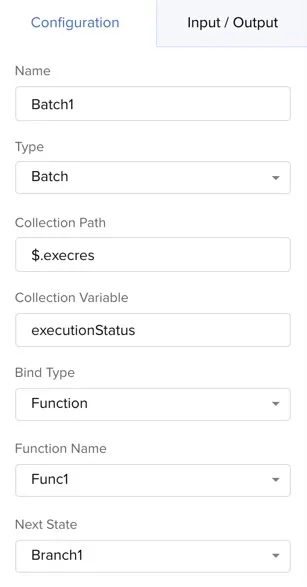
You can bind the batch state to a specific function or circuit, by choosing the bind type and the circuit reference name or function name from the drop down lists. You can configure the following properties of a batch state:
- Collection path: The path that contains the JSON list, written in the JsonPath syntax
- Collection variable: The variable that is assigned to contain the JSON output
For example, a JSON input contains a list of two JSON objects as an array as follows:
{
"userList":[{"name":"Paul"},{"name":"Max"}]
}
We pass this input to a batch that is associated with a function. We define the collection path as $.userlist, indicating that the object containing the list array is available in that path. We enter the collection variable as user, assigning it as the variable to hold the output.
If we enter the number of jobs as 2, the associated function, which returns the name object, is called two times parallelly and the input is passed to it. The output of the first iteration is generated as:
{
"userList": [{"name": "Paul" },{"name": "Max"}],
"user":{"name": "Paul"}
}
The output of the second iteration contains the value of Max assigned to the name parameter:
{
"userList": [{"name": "Paul" },{"name": "Max"}],
"user":{"name": "Max"}
}
Both iterations happen simultaneously. If you assign $.userlist in the result path of the batch, you can pass the output containing the JSON list to the next state.
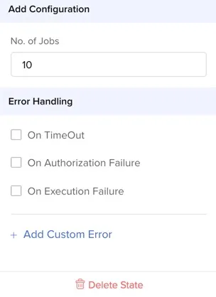
Catalyst can execute a maximum of 10 jobs in a batch state. You can define this in the batch’s configuration.
The batch state supports default and custom error handlers similar to the circuit state. It has one action for its default or custom error handler: Retry. Refer to the Function section for information about retry and custom error handlers.
You can write your own logic for the actions to be performed if all retry operations fail. For example, you code for the circuit to re-execute, or end it and send a notification about the issue.
You can configure the input, output, and result paths of a batch state.
You can also pass parameters to the function being processed in the batch state dynamically, similar to the function state. Refer to the Function section for details.
The execution log of the circuit provides links to the function or circuit that was executed, and to the Catalyst Logs that contains the log of that function, for a batch state.
Success
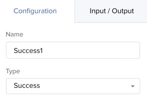
The success state is an end state that is used to determine the success of the previous operation or task executed in the circuit. It is used to represent a successful execution for the user’s reference.
For example, you could use the success state along with a failure state in a branch to mark the outcomes of two processes in it based on different conditions, or use it after a function execution to indicate the success of the execution.
The success state does not have any configuration or properties, as it is the final state of that particular path in the circuit. You will not be able to set any next state after it.
You will also not be able to configure an input path or output path for a success state.
Failure
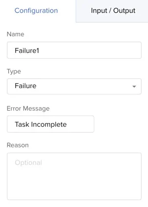
The failure state is also an end state that is used to determine the failure of the previous operation or task executed in the circuit. It is used to represent a failed execution for the user’s reference.
You can use the failure state similar to the success state, and in other scenarios to mark the failure of a process or a task execution.
You will not be able to set a next state for a failure state, as it is the final state of that particular path in the circuit. You can provide an error message and an optional reason in the state for your reference, if this state is traversed.
You will not be able to configure an input path or output path for a failure state.
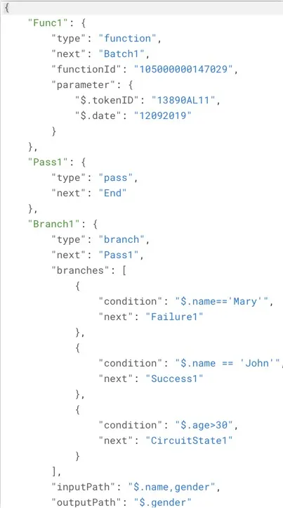
JSON Code
As mentioned earlier, you can also directly code a circuit in the JSON format from the console.
The Code View section enables you to work on the code directly. The code is automatically generated as you drag and drop states in the flow diagram. Refer to the Implementation section for more information.
A state name is a JSON object and its properties are the key-value pairs of that object. Properties like type and next are commonly used for all states. If a state does not mention the next key, it is the last state in the circuit. If a state is not referred as next in any other states, it is the first state of the circuit.
You must follow the standard JSON syntax while coding a circuit.
A sample code snippet of circuit is shown below:
Circuit URL
When you create a circuit in your Catalyst project, a unique invocation URL will be generated for it automatically. You can trigger the circuit from this end point URL. You can implement this URL in your application’s code or use it as you require.
You can obtain the URL of a circuit from the console.
A Circuit URL is in the following format:
This URL must be invoked with the HTTP POST method.
The project_domain_name is the domain name of your project. The environment_type is development, if you are working in the development environment. Otherwise, the environment_type is not present in the URL.
Last Updated 2025-11-07 17:21:15 +0530 IST
Yes
No
Send your feedback to us