Implementation
The implementation section covers configuring and testing a Catalyst circuit from the console. To implement circuits in your Catalyst application, refer to the Java SDK, Node.js SDK, Python SDK and API documentation.
Create a Circuit
To create your first circuit in your project from the Catalyst console:
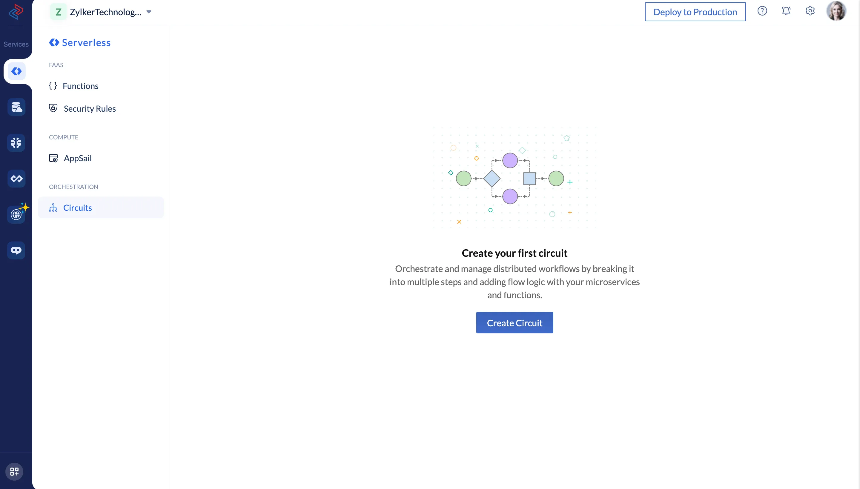
- Navigate to Circuits under Orchestration in the Catalyst Serverless console and click Create your first circuit.
- Enter a name for the circuit and click Create.
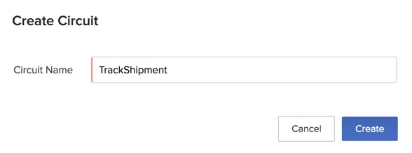
The circuit will be created and the Builder View will open.
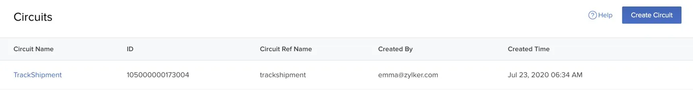
You can click the arrow mark near the circuit’s name to navigate to the Circuits page. A unique Circuit ID and a unique Circuit Reference Name will be created for the circuit. This is the reference name that is used when you nest a circuit using the circuit state, or when you associate a batch state to a circuit. The circuit ID is used to refer to the circuit when working with the SDKs and API.
Configure a Circuit
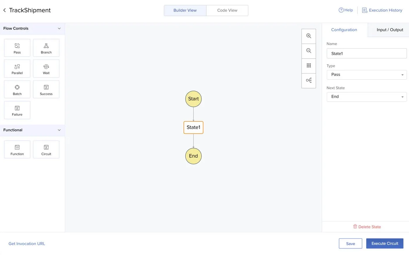
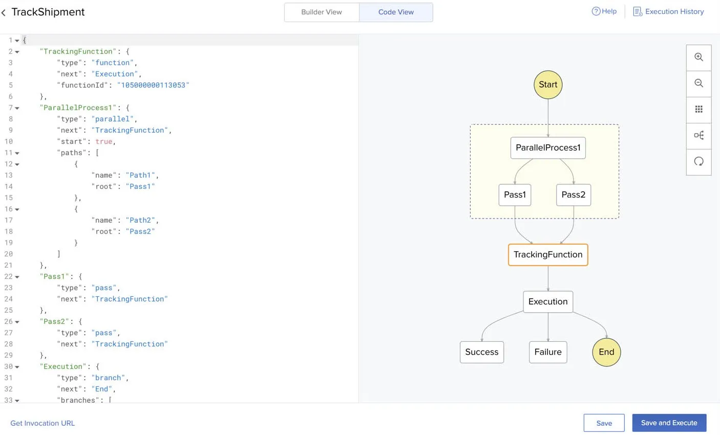
Let us now configure the circuit that we created. Click the circuit’s name from the Circuits page to open the Builder View. You can now drag and drop states from the left panel to the circuit.
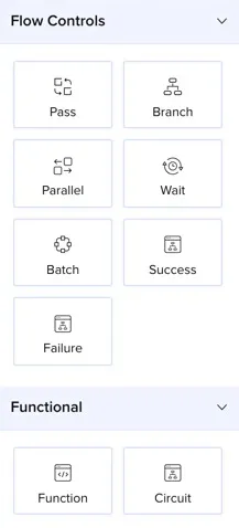
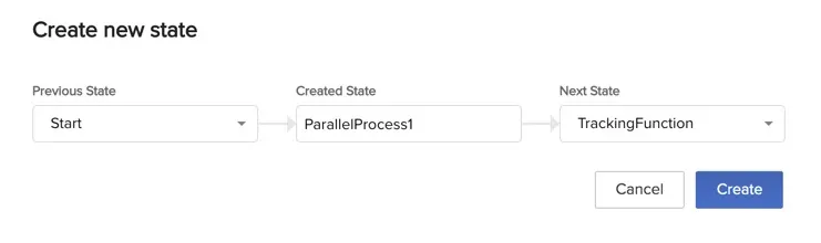
When you drag and drop a state, a pop-up window will open. You can enter the details of the state, such as the state name, previous state, and next state in it. Click Create to create the state.
The state will be displayed in the flow diagram. You can now configure the state, provide input and output paths, remove parameters, delete states, and more.
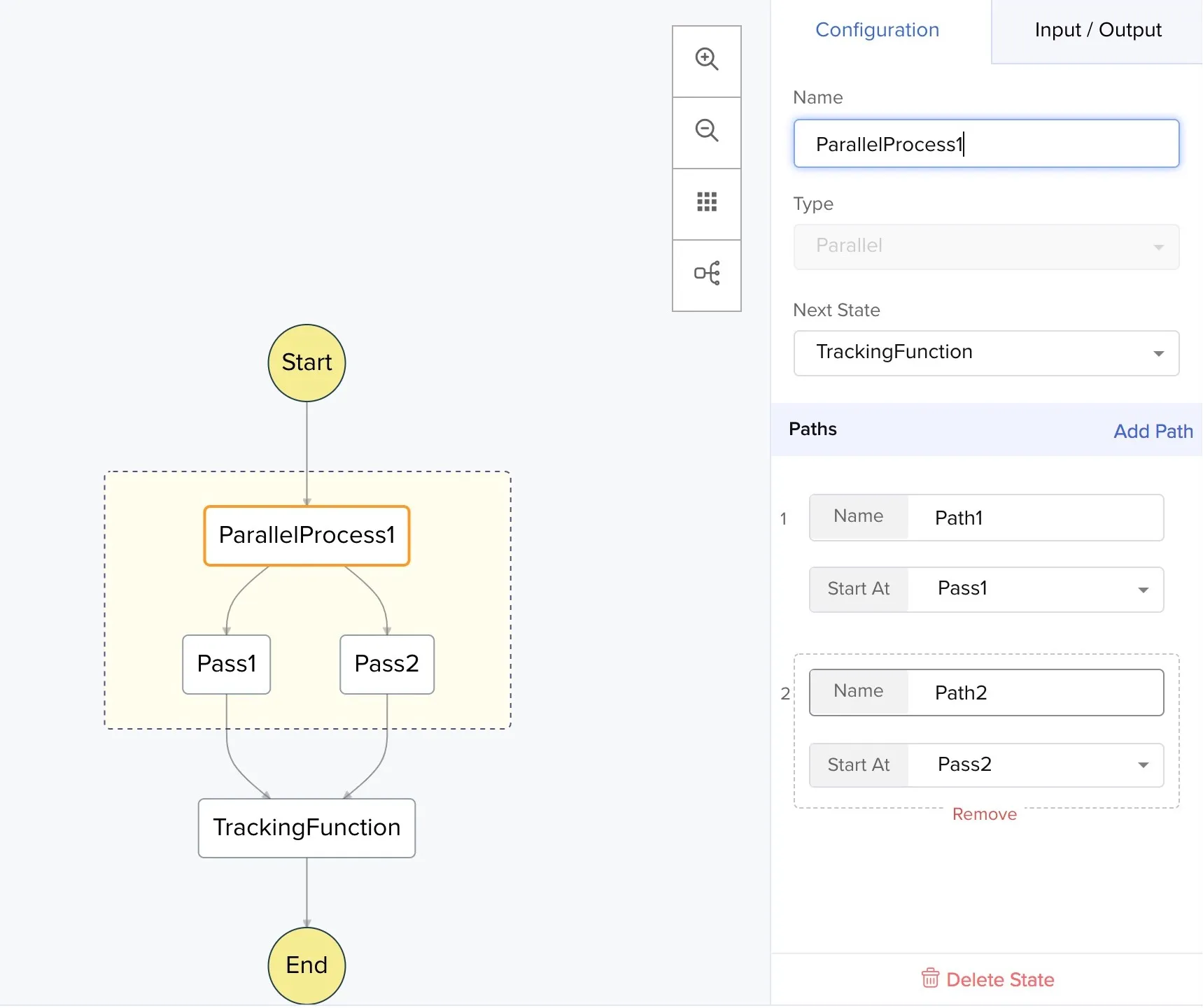
Refer to this Key Concepts section on states for details about the configuration and properties available for each state.
You can also change the view to horizontal, auto arrange the states in the flow diagram, zoom in, or zoom out using the icons on the right side.
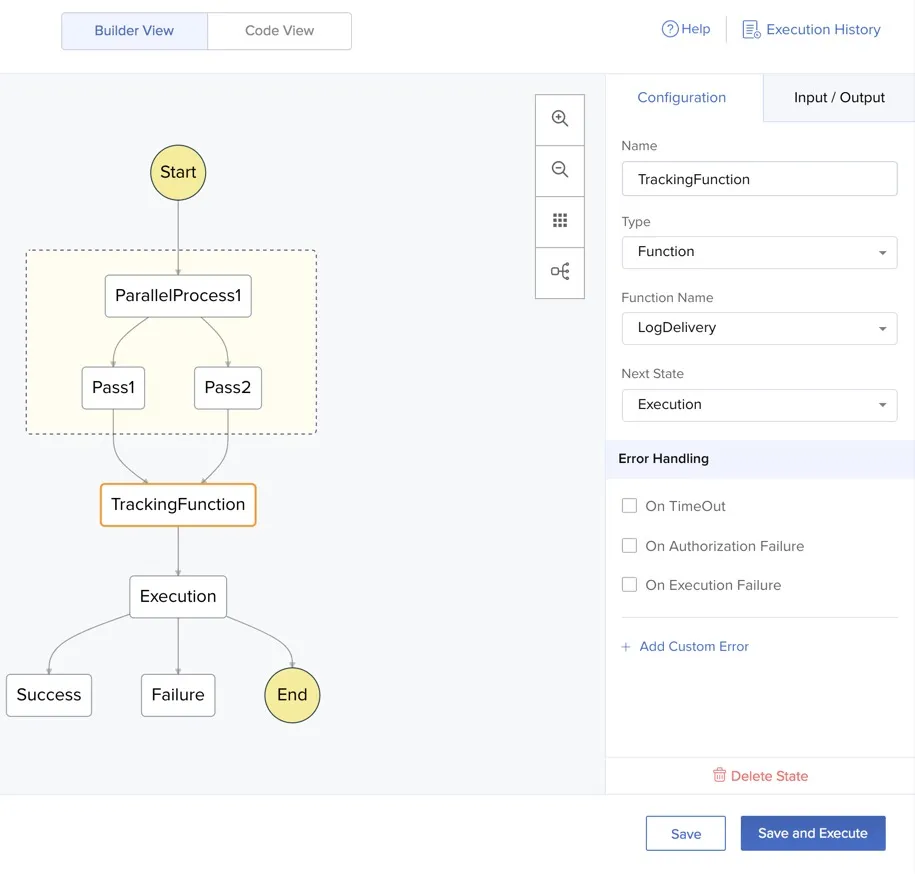
You can also click Code View to view the auto-generated JSON code of the circuit. Any changes that you make in the code or in the diagram, will be reflected in the other automatically. You can click the refresh icon if the live reflection is delayed.
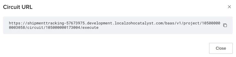
You can access the Circuit URL by clicking Get Invocation URL from the bottom left corner.
Once you have configured the circuit, click Save.
Circuit Compilation Errors
Before you execute a circuit, Catalyst performs a compilation error check in the circuit’s configuration or structure. When you click Save or Save and Execute after configuring a circuit, Catalyst will immediately run a compilation check on the circuit, and list out the errors in its state configurations, design, and logic flow.
These are non-dependant and possible errors that Catalyst identifies before running the circuit with the input you provide. This will enable you to verify and perform fixes in your circuit’s design and configuration even before you execute it.
For example, in the circuit shown below, the parameters of two branch states have not been defined. Additionally, the states are configured in a cyclical loop without defining any conditions to end the loop. When you click Save or Save and Execute here, Catalyst will immediately display these errors as shown below.
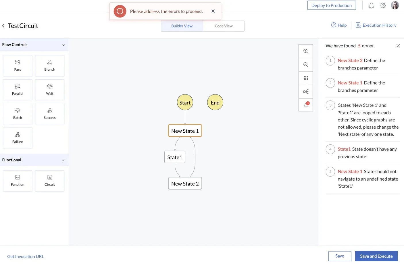
After you initiate a circuit’s execution, Catalyst will be able to detect dynamic errors related to the test condition, data flow, and other run time issues, and provide you detailed logs of each event. This will be explained in the next section.
Execute a Circuit
You can execute a circuit with different test conditions and inputs, and view the generated results.
To execute a circuit:
- Click Save and Execute from the bottom-right corner of the circuit’s page.
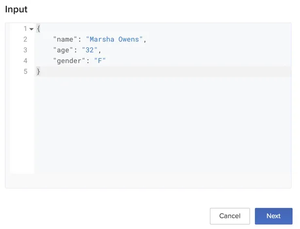
- Provide the input for the circuit in the JSON format as key-value pairs and click Next.
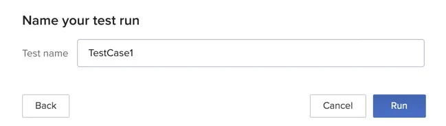
- Provide a name for the test case and click Run.
You can view the live execution of the circuit from the View Graph section.
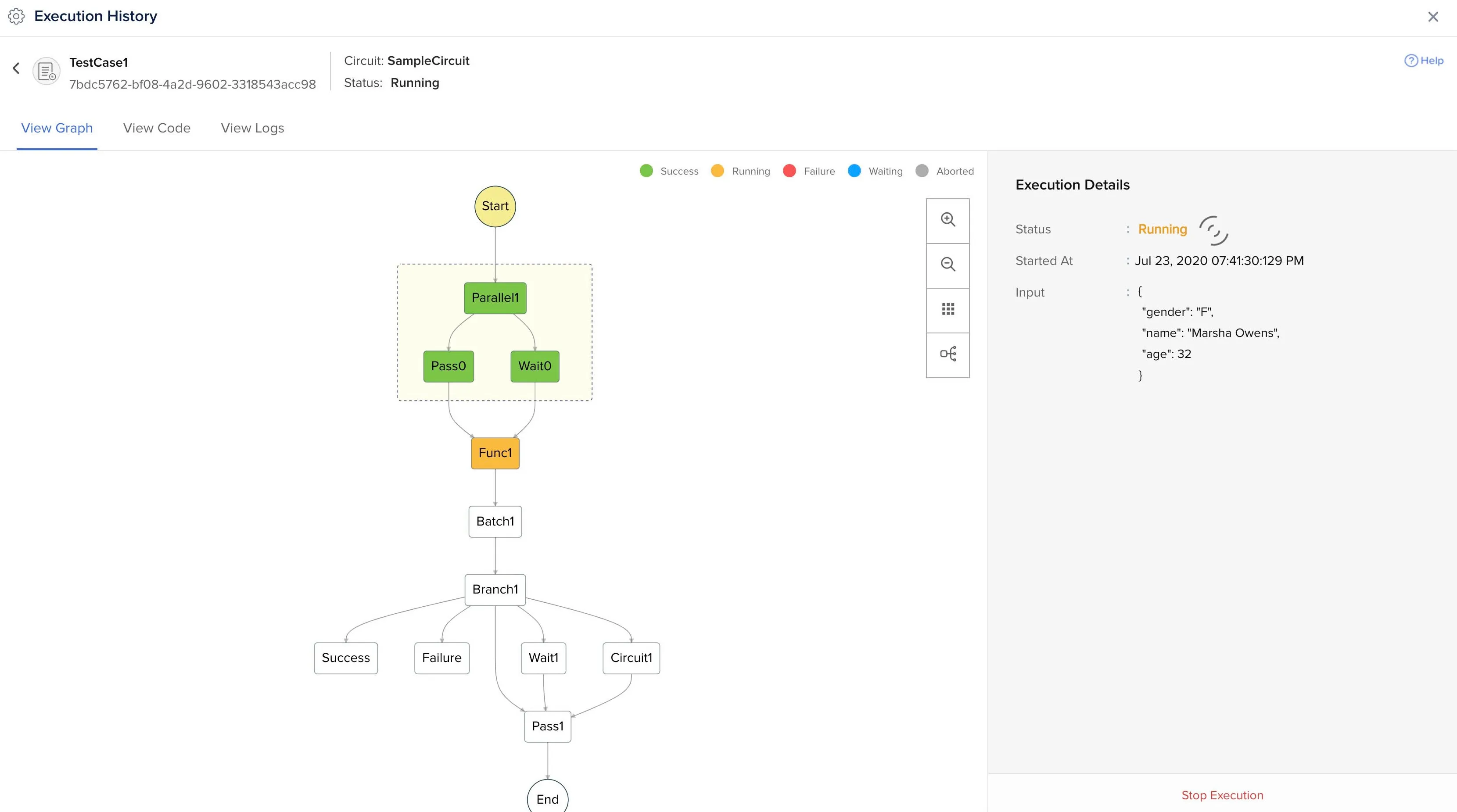
Once the circuit has been executed, you can view the execution details, such as the input, output, and the duration of the execution, from the right panel. You can click Stop Execution to stop it at any time.
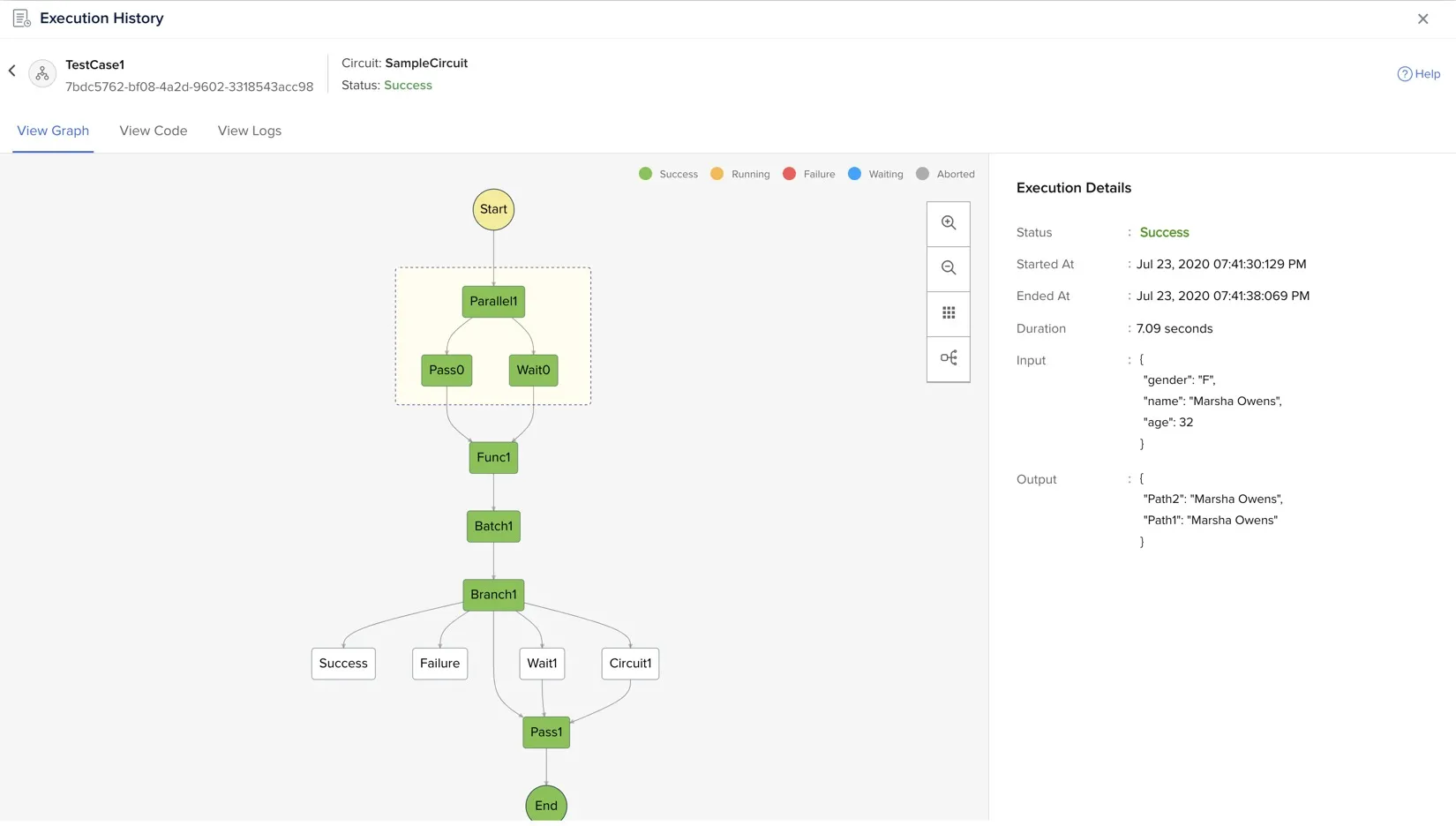
You can view the paths that were traversed in the circuit, the status of each state represented by a color code mentioned at the top, and the overall status of the circuit execution as well.
The View Graph is a part of the execution history of the circuit. The next section covers details about it.
Execution History of a Circuit
You can access the execution history of a circuit any time by clicking View Execution History on the top right corner from the circuit’s page.
This opens a list of all the executions of the circuit, along with their unique Execution ID and other details.
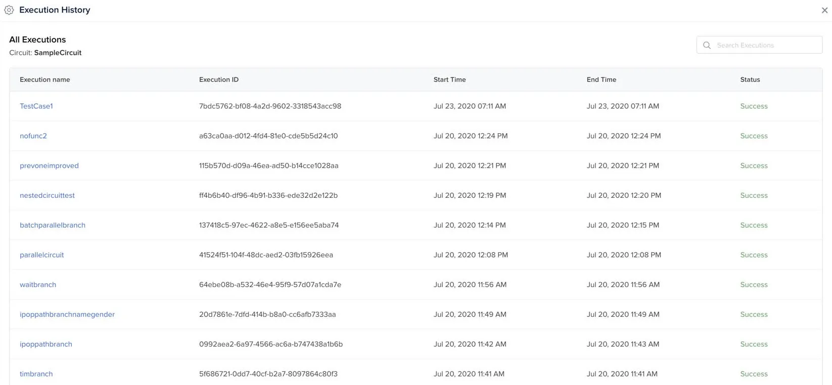
You can open a particular execution to check its execution graph, the circuit’s code, and the execution’s logs. Click View Logs to view the logs of the execution.
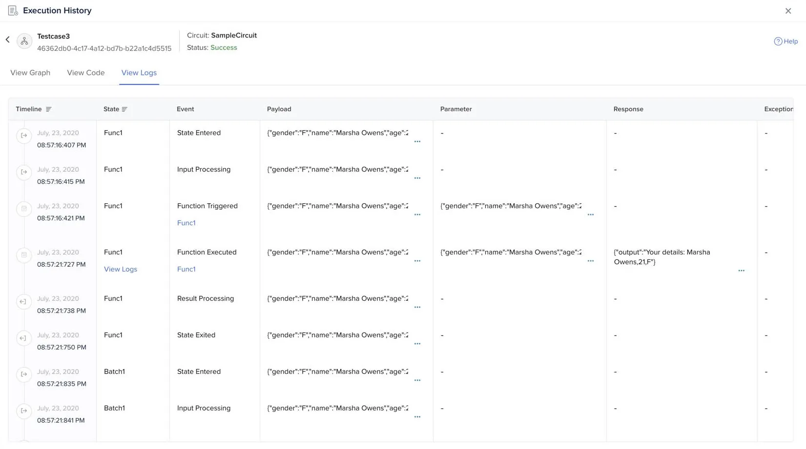
The logs provide details of the task execution in each state. They display the following details:
- Timeline: Displays the date and time of a particular event in a state, along with icons to indicate the event type
- State: Refers to the state in which a particular event is executed
- Event: Refers to the specific event that occurred in the state. The common events of all states include: State Entered, Input Processing, Result Processing, State Exited. Some states have additional custom events. For example, the wait state has a State Time Waiting event that lasts until the wait time ends. The function state has Function Triggered and Function Executed events after the Input Processing event.
The success and failure states only have Success State Reached and Failure State Reached events, since they are end states. The beginning and the end of the circuit executions are marked by State Machine Triggered and State Machine Executed events. - Payload: Refers to the input JSON that is transmitted from one state to the next in the circuit. The payload of a state is its input which will be processed by it.
- Parameter: Refers to the additional parameters that are provided by the user. Parameters can be provided in the function and batch states.
- Response: Refers to the output generated by the state after its processing. If any values are given in the output path or the result path of the state, the output is modified accordingly.
- Exception: Refers to any exceptions that might be generated by the state. If the state’s processing fails, you can view the exception details from here.
The detailed log enables you to effectively assess failures and detect bugs in each state’s execution in a circuit. As mentioned earlier, the logs of the function, circuit, and batch states contain links to the function’s page, Catalyst Logs, or to the nested circuit’s logs for easy access.
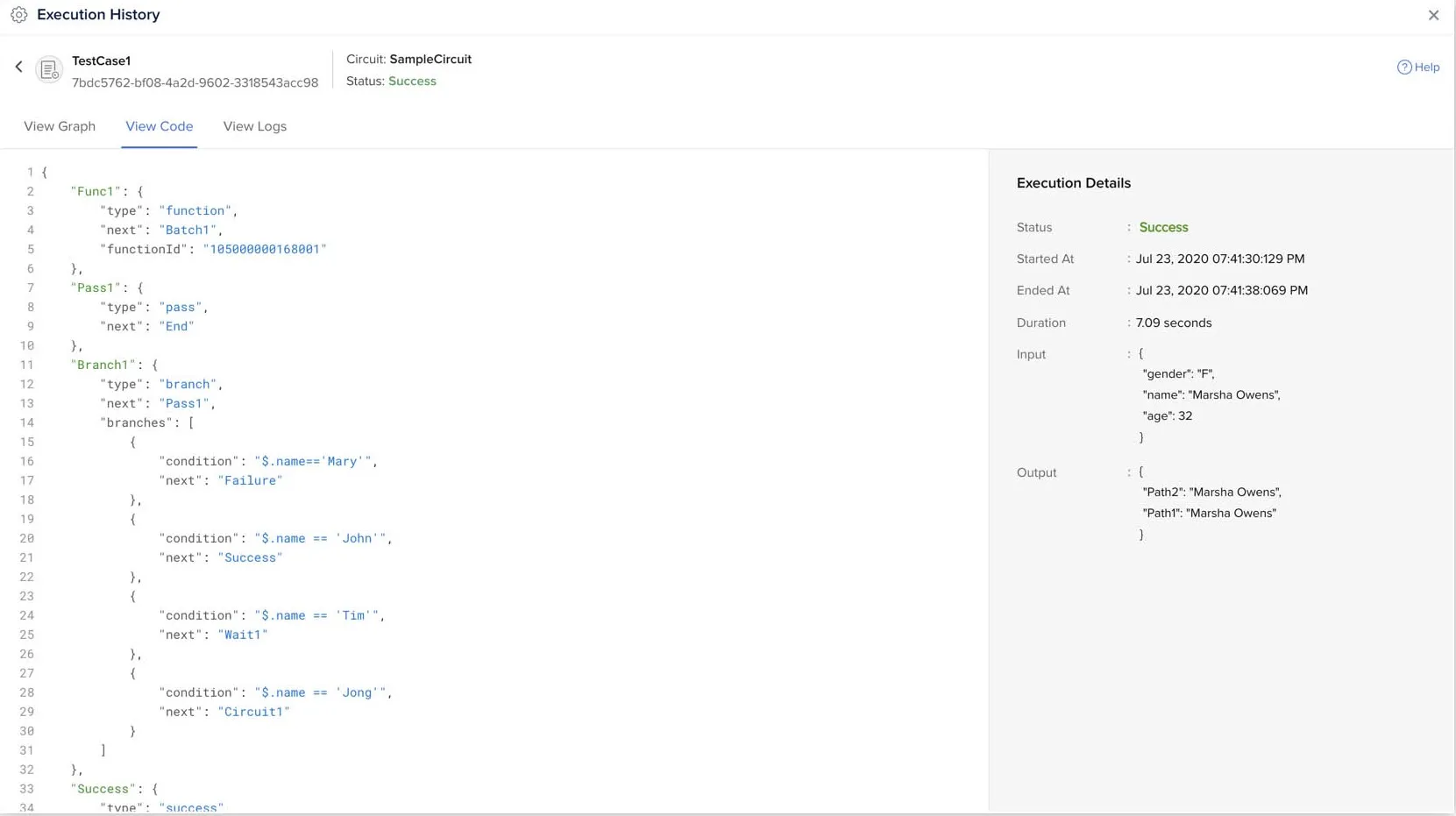
The View Code section displays the circuit’s code, along with the execution details.
Rename a Circuit
To rename a circuit from the Catalyst console:
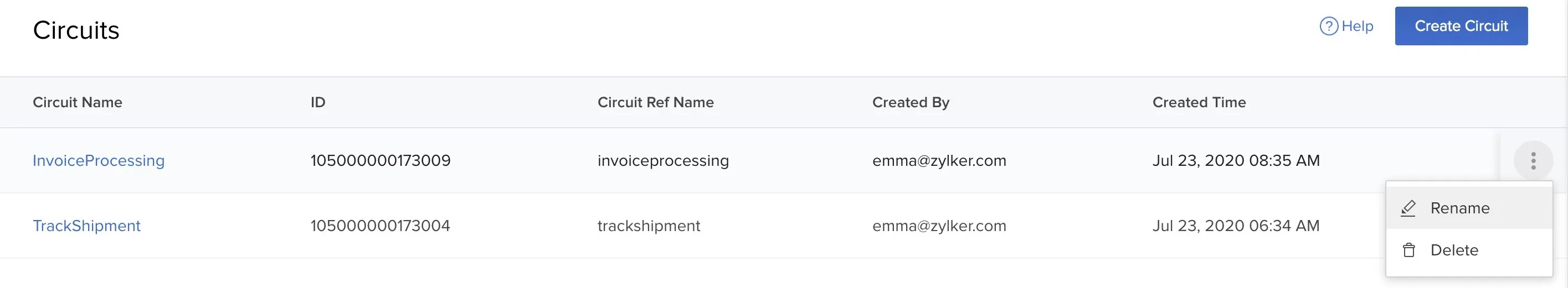
-
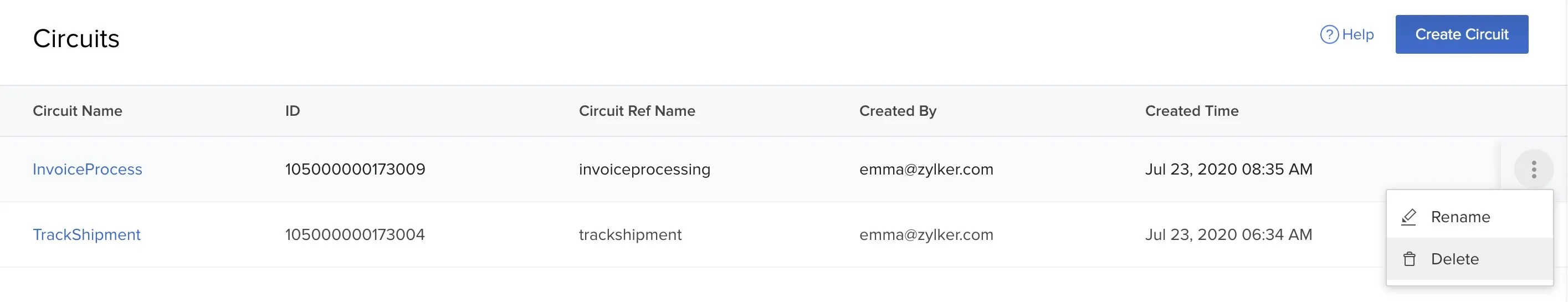
Click the ellipsis icon for the circuit in the Circuits page, and click Rename.
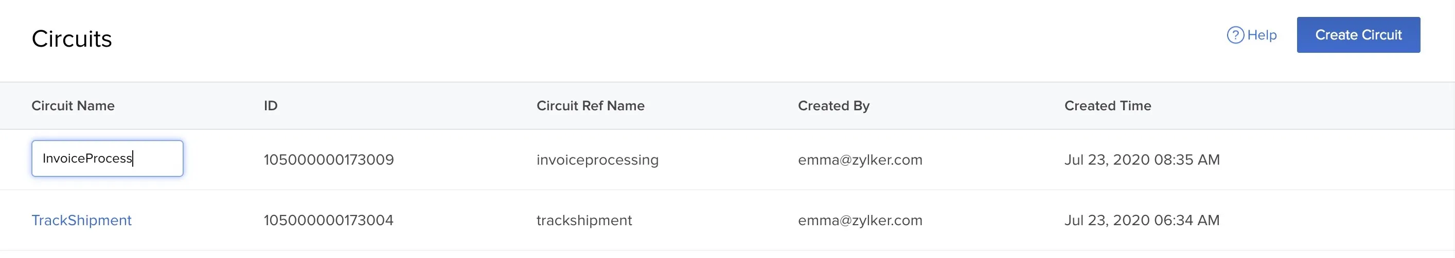
-
Enter a new name for the circuit and press Enter.
Delete a Circuit
To delete a circuit from the Catalyst console:
- Click the ellipsis icon for the circuit in the Circuits page, and click Delete.
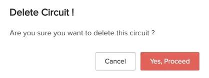
- Click Yes, Proceed in the confirmation window.
Last Updated 2025-02-19 15:51:40 +0530 IST
Yes
No
Send your feedback to us